Saturday 20 February 2016

Using the ESP8266 with DIoTY.co

The ESP8266 has come a long way since it first became available in 2014.  In the beginning, little was know about the $5 microcontroller that includes WiFi capability.  And, the little information that could be found, was all in Chinese.

By now, 2016, there are over 10 different version of the ESP8266 available. There's plenty of information on the web, a lively community forum and even multiple software development kids SDK's.

Recently Emanuele P, a DIoTY.co user, contacted me with some questions on connecting the ESP8266 to the DIoTY cloud.  Later, when he got everything working fine, he shared his code... a .ino file!  As I hadn't tried out ESP8266 Arduino before, I thought I'd give it a go and found out it was by far the easiest and quickest way to get started with ESP8266, at least for those people who have some Arduino experience.

So, here's how to get started.  
  • First download and install the latest stable version of the Arduino software: https://www.arduino.cc/en/main/software.  If you already have the Arduino software, make sure you have a least version 1.6.5.
  • Start Arduino, open Preferences window and enter http://arduino.esp8266.com/stable/package_esp8266com_index.json into the "Additional Board Manager URLs" field
  • Next go to the Tools > Board > Board Manager and install ESP8266
  • Next go to the Tools > Board and select ESP8266

In order to be able to connect to DIoTY's cloud you'll need some MQTT libraries.  You can find many different ones on the net, but I went for the latest version of Nick O'Leary (@knolleary) PubSubClient. This is an updated version of the one I used in my earlier blog post which now includes support for ESP8266.  You can still download it from GitHub and install it as explained in Arduino's guide.


The good thing about Nick's PubSubClient is that it comes with some sample code.  This is a great starting point, so I've stripped it further down and configured it to connect to DIoTY.  The result can be found here on GitHub.  Download it and import it into your Arduino workspace.   Next change the userId's and passwords for your WiFi network and DIoTY account and check it compiles successfully.

In this simple example, we will connect to the DIoTY Cloud MQTT service.  When we are successfull, we will publish to say after how many attempts we were successful.

Next we will subscribe to a topic "/<yourDIoTYuserId>/ESP8266/inTopic".  This is the same topic we will configure in the mobile app as a switch.  Toggling the switch on the mobile app will cause the app to publish 'true' and 'false' to the topic.  This will be picked up by the ESP8266 who will toggle a led on and off.

To be able to transfer the program onto the ESP8266 you'll need some kind of TTL serial converter.  I bought the CH340G, but you'll find other similar products when you search around a bit.  You'll also need some 3.3V power source able to deliver 1A or more.

Here's the pin layout of the ESP-01 and how you should connect it to upload your software:

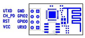
  • GND:      ground of your 3.3V power supply and GND of your TTL serial converter.
  • UTXD:    TTL serial converter RX
  • GPIO02: do not connect
  • CH_PD:  plus side of your 3.3V power supply
  • GPIO0:   ground of your 3.3V power supply
  • RST:       do not connect
  • URXD:   TTL serial converter TX
  • VCC:      plus side of your 3.3V power supply
Now you're ready to upload your program much like you would upload a program to your Arduino.  If you get an error message, switch of the power for a few seconds before retrying.

Once you got the program loaded, have a look at the serial monitor output and you should see your ESP connecting to your WiFi and after that also to DIoTY.  Once connected successfully to DIoTY the program will post it was successful to the topic /<yourDIoTYid>/ESP8266/connected.  You can confirm this by login in onto DIoTY's website and navigating to "My DIoTY".

Now that we got this far, it's time to power off the ESP8266 and rewire it for business.  Unplug it from the TTL serial converter as we don't need this one anymore.  Wire GPIO0 to the minus side of a LED (short leg) and wire the plus side of the LED (long leg) to the plus side of your 3.3V power supply.  Most LED's can handle 3.3V, but if yours can't don't forget to put a resister in between.

Finally we need to configure the DIoTY mobile app with a switch to control the LED.  If you haven't already installed the mobile app have a look at my previous post: it shows you where to get it from, how to log in and add new things.  So, now that we know how that works, add a new thing of type "switch".  Give it a name of your liking and configure it with topic /<yourDIoTYid>/ESP8266/inTopic.

And that's it...  Switch on your ESP8266, wait for it to connect to your WiFi and the DIoTY cloud and switch the led on and off using your mobile... from anywhere in the world... or for right next to it like in this short video below ;-)


By connecting GPIO0 to the signal input of a relay, you can now switch on and off just about anything rather than just a little LED.

Friday 3 April 2015

DIoTY mobile app to control your IoT projects


In my previous posts, I've shown how to publish your sensor data to DIoTY's MQTT Cloud infrastructure.  One of the benefits of publishing it to the cloud is that by doing so you can access the information from anywhere.  You can use an app like myMQTT to display the raw data but often what we really want is something a bit more practical and that's where the new app from DIoTY comes in.

Note that to use the app, you must be registered on DIoTY's website so that you have a user-id and password.

Next go to the appStore (google play or iStore) and download the DIoTY app:

Get it on Google Play

Get it on iStore

After installing and opening the app, you need to log in using your DIoTY credentials.  Your user name is your email address used while registering and your password is the one received in your mailbox after login into DIoTY's website for the first time.


Next you need to add your things to the mobile app's configuration.  You do this by clicking on Menu  (the three lines in the top right corner) and then Add. Now you will see the following screen:


Let's start by adding the temperature sensor from our previous blog post: Connecting Arduino with DIoTY's Cloud Infrastructure.

Fill in a name: for example "Living room temp".
Next choose a type: for a sensor we should choose "readonly value" as we can just read the sensor value, not update it.

The screen updates as soon as you choose the type and requests values for topic and unit.

As topic you will need to use the topic where your sensor is publishing.  By tapping the topic area it will automatically start filling the topic with your email address, as this is where your app has publish and subscribe rights, so all you need to do is add the rest of the topic tree used.  If you have followed the blog mentioned above you need to add "temp" to the topic.  The complete topic looks like "/youremail@gmail.com/temp".

For unit, you need to either type Celcius (or Fahrenheit if you adjusted the calculation in previous blog post to give the temperature in Fahrenheit instead).

Next hit the Save button and you will go straight to the main screen:


Now, every time you log into the DIoTY app, it will show you the latest temperature measured by your sensor.  Note that you don't have to log out an back in every time.  If you do not log out, the app will remember your credentials and on startup it will go straight to the main screen.  However, be aware that if your phone's cpu went to sleep, the connection with the DIoTY server might have been lost.  In that case, just pull the screen down and the app will reconnect and update your sensor data again.

If you made a mistake in the topic, or you want to edit the name or unit, drag the item you want to change towards the left and you get an edit button as shown below:


Tab on the edit button and you get a chance to edit any of the fields or delete the selected item altogether:


Although you could change the type at this point, you should not.  If you want to change the type, it is always safer to delete you thing first and then add a new one with the new type. Currently 3 different types are supported.  The readonly value as demonstrated above, the on/off switch which you could use to control a relay and the range/slider which can be used to create a dimmer or a thermostat. Hint: if you wanted to test the app before you had your sensors/actuators in place, you could define both, a slider and a readonly thing pointing to the same topic.  You will then see your readonly value following your slider as below:

Hope you enjoy using DIoTY's app...

Friday 5 December 2014

Raspberry PI, sensors and DIoTY MQTT cloud

In a previous post I showed how to connect your Arduino to DIoTY's MQTT cloud infrastructure and make your sensor data instantaneously available to any MQTT client.

This time round, I'm going to work with a Raspberry PI and a DHT22 Humidity Temperature Sensor Module.  I will use MQTT to publish the values received from the sensor and use the new and improved DIoTY website to view the how warm and humid it actually is in my office!

We use following hardware for our example:

  • Raspberry PI B+ (but any model should do)
  • micro SD card (or the one matching your Raspberry PI model)
  • USB wifi nano
  • Type-T GPIO Expansion Board Accessory for Raspberry Pi B+
  • DHT22 Humidity Temperature Sensor Module
  • breadboard and some wires

I assume most readers already have their Raspberry PI up and running, but for those who are new to Raspberry PI, here's very brief how you get that far:
  1. Download the OS image from http://www.raspberrypi.org/downloads/ 
    • I used the Raspbian Debian Wheezy
  2. Copy the image to your SD card
    • check the volume of your SD card using diskutil list
    • unmount the volume (eg if the volume found is called disk1 then  execute diskutil unmountDisk /dev/disk1)
    • copy image with sudo dd bs=1m if=2014-09-09-wheezy-raspbian.img of=/dev/disk1 (adapt image name and volume name to match yours)
  3. Configure your Rasberry PI
    • startup your Raspberry PI with ethernet plugged in and log in with user pi and password raspberry
    • start configuration with sudo raspi-config
      • expand filesystem
      • change pi password to your own
      • change timezone to yours under internationalisation
      • finish with reboot and log in with your new password
  4. Update the OS
    • execute sudo apt-get update to get the latest (security) updates
  5. Configure the wifi (I'm using a wpa with  a wep key on my router)
    • execute sudo vi /etc/wpa_supplicant/wpa_supplicant.conf and add the following network section (filling in your values for ssid and hex web_key0):
      network={
         ssid="MyNetworkName"
         wep_key0=abcdef0123456789
         key_mgmt=NONE
        }
    • install wicd-curses
      • execute sudo apt-get install wicd-curses
    • plug in the wifi stick and configure by running sudo wicd-curses
      • configure network --> connect automatically using WEP key
Unlike with Arduino, with a Raspberry PI we can choose what programming language we'd like to use.  As I've been working a lot with Node.js lately and started liking it I'll do this exercise with Node.  

Node is not the ideal language when it comes to real time programming.  In fact, you won't find any pure Node modules that interact with the GPIO.  You do find libraries for this in C however which you can wrap in your Node module.  Even better, as Node.js is so well adopted in the open source community you'll often find those wrapper modules readily available for your sensor... and the DHT22 is no exception (see Node Package Manager website for node-dht-sensor).

So let's get started!

First we need Node and NPM installed.  There are several ways of doing this, but I prefer to do it the safe (or long, whichever you prefer) way.  Installing Node.js is done using the following set of commands:
     sudo apt-get install python g++ wget libssl-dev
     mkdir /tmp/nodejs && cd /tmp/nodejs
     wget http://nodejs.org/dist/node-latest.tar.gz
     tar xzvf node-latest.tar.gz && cd node-v*
     ./configure
     make
     sudo make install
Note that those make commands will take time!

Next install the Node Package Manager:
     curl https://www.npmjs.org/install.sh | sudo sh

The link above on the NPM node-dht-sensor package shows us how to install the module and gives also some sample code on how to use it.  All we have to do is adapting the sample program to start talking to our MQTT cloud service.  And yes, there is also an MQTT package available which does all the hard work on the MQTT side for us.  So lets create a new directory for our project in our home drive and install both packages required:
     cd 
     mkdir dht22 && cd dht22

The node-dht-sensor package requires the bcm2835, so let install that first:

     wget http://www.airspayce.com/mikem/bcm2835/bcm2835-1.38.tar.gz
     tar zxvf bcm2835-1.38.tar.gz
     cd bcm2835-1.38
     ./configure
     make
     sudo make check
     sudo make install

Now we can install both node packages:
     cd ~/dht22
     sudo npm install node-dht-sensor
     sudo npm install mqtt

The node-dht-sensor module comes with a test program located under ~/dht22/node_modules/node-dht-sensor.  Copy test.js to your root project folder ~/dht22 and make the changes as indicated below:

// Module node-dht-sensor demo
// Reads relative air humidity from DHT sensor

var fs = require('fs');

var mqtt = require('mqtt')
  , host = 'mqtt.dioty.co'
  , myUserId = 'xxxxxx@gmail.com'  // your DIoTY userId
  , myPwd = 'xxxxxx'               // your DIoTY password
  , client = mqtt.createClient(1883, host, {username: myUserId, password: myPwd});

var sensorLib = require('./node_modules/node-dht-sensor/build/Release/node-dht-sensor');

var sensor = {
  initialize: function() {
    this.totalReads = 0;
    return sensorLib.initialize(22, 4);
  },

  read: function() {
    var readout = sensorLib.read();
    this.totalReads++;
    console.log('Temperature: '+readout.temperature.toFixed(1)+'C, humidity: '+readout.humidity.toFixed(1)+'%'+
                ', valid: '+readout.isValid+
                ', errors: '+readout.errors);
    fs.appendFile('log.csv',
      new Date().getTime()+','+readout.temperature+','+readout.humidity+',"'+(readout.checksum ? 'Ok' : 'Failed')+'",'+
readout.errors+'\n',
      function (err) { });

    if (readout.isValid && readout.checksum) {
      client.publish('/'+myUserId+'/office/temp', readout.temperature.toFixed(1).toString(), {retain: true});
      client.publish('/'+myUserId+'/office/humidity', readout.humidity.toFixed(1).toString(), {retaintrue});
    }

    if (this.totalReads < 300) {
      setTimeout(function() {
        sensor.read();
      }, 500);
    }
  }
};

if (sensor.initialize()) {
  sensor.read();
} else {
  console.warn('Failed to initialize sensor');
}

We will run this with the command sudo node test,js but let's first look at the hardware side.  This as well is pretty easy.  The dht22 sensor module I have comes with a 4.7kOhm resistor build in, but if that's not the case for you then you should put one in between the VCC and Data line of your sensor.  Apart from that we have just 3 connections to make:

  • Connect the VCC (+) of your sensor to the 3.3V (pin 1) or your Raspberry PI
  • Connect the GND (-) of your sensor to the GND (pin 39) of your Raspberry PI
  • Connect the Data (S) of your sensor to the GPIO4 (pin 7) of your Raspberry PI


So now that we are all set up and as specified below, we will run the test script with the command sudo node test.js
This start writing temperature and humidity levels to:
  • the console
  • a log file
  • our DIoTY MQTT Cloud infrastructure
This last we can see on www.dioty.co by following the "My DIoTY" link you will see after signing in.

Monday 28 July 2014

Connecting Arduino with DIoTY's Cloud MQTT Broker

In my previous post I showed how to get started with DIoTY's Cloud MQTT Broker.  Now that you are all set up, proved to yourself all is working, it's time to do something a little more interesting.  So today we will use an Arduino Uno and a temperature sensor to publish the current temperature to the MQTT Broker.

We use following hardware for our example:
  • Arduino Uno with ethernet shield
  • One-wire temperature sensor (DS18B20)
  • 4.7k resistor
  • breadboard and some wires
Make sure you verify the the pin layout before wiring as incorrect wiring can damage the sensor and the arduino + ethernet shield (and we accept no liability at all).

Wiring is done as in the picture below:


Next we need to load the software to the Arduino.  For this, first import the following two libraries into your Arduino Development Environment: OneWire and PubSubClient.

The latest OneWire library can be downloaded from Paul Stoffregen's site.
The latest PubSubClient library can be downloaded from GitHub.  Full documentation is found on Nick O'Leary's site.

If you haven't imported libraries before take a look at following guide.

Once the libraries are in place it's just a matter of copying and pasting the following code into the sketch, replacing the bits in red with values suitable for yourself.  Note that yourUserID is the email address with which you registered at DIoTY.  You need to use that same full email address at the start of your topic as you will only have authorisation under that subtree.


#include <SPI.h>
#include <PubSubClient.h>
#include <Ethernet.h>
#include <OneWire.h>

#define DEBUG
#ifdef DEBUG
  #define DEBUG_PRINT(x)  Serial.println (x)
#else
  #define DEBUG_PRINT(x)
#endif

byte mac[]= {0x90, 0xA2, 0xDA, 0x0D, 0x88, 0x5E} ; // change by your arduino mac address
char userId[] = "yourUserID"; // use your DIoTY user id (=email address)
char passwd[] = "yourPassword";  // use your DIoTY password
char server[] = "mqtt.dioty.co";
unsigned int port = 1883;
char topic[] = "/yourUserID/temp"; // topic where to publish; must be under your root topic
EthernetClient client; 
PubSubClient arduinoClient(server, port, 0, client) ; //no callback function is specified as we only publish


void setup() {                
  Serial.begin(9600); 
  DEBUG_PRINT(F("Initialisation"));
  beginConnection();
}

void beginConnection(){
  DEBUG_PRINT(F("Entering beginConnection"));
  if (Ethernet.begin(mac) == 0) {
    Serial.println(F("Failed to configure Ethernet using DHCP"));
    exit(-1);
  };
  DEBUG_PRINT(F("Obtained IP Address:"));
  DEBUG_PRINT(Ethernet.localIP());
  if (arduinoClient.connect(NULL,userId,passwd)) {
    DEBUG_PRINT(F("Connected to MQTT Server..."));
  } else {
    Serial.println(F("Failed to connect to the MQTT Server"));
    exit(-1);
  }
}

// reconnect after network hiccup      
void reConnect(){
  DEBUG_PRINT(F("Entering reConnect"));
  
  if (arduinoClient.connected()){
    DEBUG_PRINT(F("arduinoClient is connected"));
  } else {
    DEBUG_PRINT(F("arduinoClient is not connected"));
      if (Ethernet.begin(mac) == 0) {
        Serial.println(F("Failed to configure Ethernet using DHCP"));
      };
      DEBUG_PRINT(Ethernet.localIP());
      if (arduinoClient.connect(NULL,userId,passwd)) {
        DEBUG_PRINT(F("Reconnected to MQTT Server..."));
      } else {
        Serial.println(F("Failed to connect to the MQTT Server"));
      }
  };
}
  

// DS18S20 Temperature chip i/o
OneWire ds(2);  // on pin 10
byte i;
byte present = 0;
byte data[12];
byte addr[8];
int HighByte, LowByte, SignBit, Whole, Fract, TReading, Tc_100;
char buf[10];
char lastPublished[10];

void loop(void) {

  if (arduinoClient.loop()){
    DEBUG_PRINT(F("Arduino Client loop ok"));
    
    if ( !ds.search(addr)) {
        DEBUG_PRINT(F("No more addresses."));
        ds.reset_search();
        return;
    };
    if ( OneWire::crc8( addr, 7) != addr[7]) {
        DEBUG_PRINT(F("CRC is not valid!"));
        return;
    };

    getTemp();
    dtostrf(((float)(Whole*100+Fract)/100),1,2, buf);
    
    if (strcmp (buf,lastPublished) == 0) {
      DEBUG_PRINT(F("temp not changed"));
      DEBUG_PRINT(buf);
    } else {
      arduinoClient.publish(topic, (uint8_t*) buf, strlen(buf), 1); 
      memcpy(lastPublished, buf, 10);
      DEBUG_PRINT(buf);
    };
    
  } else {
    DEBUG_PRINT(F("Arduino Client loop nok"));
    reConnect();
  }
  delay(5000);     
}

void getTemp() {
  int foo, bar;
  
  ds.reset();
  ds.select(addr);
  ds.write(0x44,1);
  
  present = ds.reset();
  ds.select(addr);    
  ds.write(0xBE);

  for ( i = 0; i < 9; i++) {
    data[i] = ds.read();
  }
  
  LowByte = data[0];
  HighByte = data[1];
  TReading = (HighByte << 8) + LowByte;
  SignBit = TReading & 0x8000;  // test most sig bit
  
  if (SignBit) {
    TReading = -TReading;
  }
  Tc_100 = (6 * TReading) + TReading / 4;    // multiply by (100 * 0.0625) or 6.25
  Whole = Tc_100 / 100;          // separate off the whole and fractional portions
  Fract = Tc_100 % 100;
  if (Fract > 49) {
    if (SignBit) {
      --Whole;
    } else {
      ++Whole;
    }
  }

  if (SignBit) {
    bar = -1;
  } else {
    bar = 1;
  }
}

After uploading the sketch to your Arduino, it will measure the temperature every 5 seconds.  When the measured temperature is different to the previous measuring, the new temperature will be published to the topic /temp topic underneath your root topic (/<yourUserID>/temp).  As the publication is retained, all clients subscribing to the topic will immediately receive the latest temperature measured and receive any changes for as long as they stay subscribed...

Tuesday 22 July 2014

Getting started with DIoTY's Cloud MQTT Broker...

In my first post I briefly explained the possibilities provided by DIoTY.co.  In this post, I'll help you getting started with the basics.  I will show you how to use the MQTT cloud broker with existing software you can freely download.  It's a quick and easy way to check you're correctly set up and to understand how MQTT works.

If you haven't done so yet, first go to DIoTY.co and sign in using a google email address.  You will receive your password to connect to the MQTT broker with your welcome email.  Note that this will take some time so do this before continuing reading this post...

When working with MQTT you will always have a client publishing messages to a topic and one or more clients receiving those messages by subscribing to that topic.

A sample publish and subscribe program comes with the free Mosquitto broker which you can download here.  It is available for most operating systems including Windows, Linux and Mac OS X and comes even with the full source if you which to compile it yourself.  I suggest you follow the installation instructions on the download page.  As you will connect to DIoTY's MQTT broker there is no need to start the mosquitto broker locally and all you are really interested in are the two programs mosquitto_pub and mosquitto_sub.

Assuming you have received your welcome email from DIoTY.co and you managed to download and install Mosquitto you're now ready to test.  For this open a couple of command line windows.  After installation, the mosquitto_pub and mosquitto_sub programs should be in your path but if not, it's probably a good idea to add them.

Publishing your first message:

You can now publish a message with the following command (just replace <your email address>, twice, with the email address you used to sign up and <your password> with the password you receive in your welcome email):

mosquitto_pub -h mqtt.dioty.co -p 1883 -u <your email address> -P <your password> -t /<your email address>/hello -m "Hello DIoTY"

DIoTY.co allows you only to publish in your own topic tree.  This means that the topic where you publish to must start with /<your email address>/.  Messages published outside of your topic tree will just be ignored.

Of course, publishing a message only makes sense when there is also at least one subscriber.

Subscribing to your topic tree:

You can subscribe to all topics in your topic tree with the following command (just replace <your email address> and <your password> like you did when publishing):

mosquitto_sub -h mqtt.dioty.co -p 1883 -u <your email address> -P <your password> -t /<your email address/#

     # is a wildcard and means that /any/subtree/will/match...
     mosquitto_sub keeps listening to the topics you subscribe to until you brake (ctr-c ; cmd-c; kill).

When you have followed this blog, the first thing you learn from this example is that messages published before the subscriber has been started will just be lost.  So whilst your subscriber is still subscribed, open another window and run again the mosquitto_pub command.  Now you will see "Hello DIoTY" appearing in your subscriber window.  Yes, it does work after all ;-)

I can hear people thinking already, when I connect with my mobile device to see the temperature at home, I don't want to wait till the temperature changes and the sensor publishes the new value.  I want to see immediately the last know temperature.  To obtain this, use so called retained publications.  Publish again the same messages as before, but this time add a "-r" to the mosquitto_pub command.  When you afterwards start a new subscriber client (either in a new window or by stopping and starting the one you have running already) you will see the retained message immediately.

Have a look at the documentation mosquitto_pub and mosquitto_sub for other options available.

Since our MQTT broker is in the cloud, you can also download a mobile application like mymqtt on your android device.  Just connect to mqtt.dioty.co, add your username, password and subscription topic and you not only see the published messages on your computer but also on your phone or tablet.

Monday 21 July 2014

The beginning...

I'm writing this blog as founder of DIoTY.co, a cloud based platform to help you experiment faster with your IoT projects.  
DIoTY currently provides you with two services, an MQTT broker and a Node-RED development tool.  I'll start with explaining what they are and what you can do with them.


MQ Telemetry Transport (MQTT) is a lightweight broker-based publish/subscribe messaging protocol.  MQTT was originally developed by IBM but is currently standardised by OASIS and is both free and royalty free.  It is rapidly becoming one of the standards for IoT/M2M.  

MQTT is a lightweight broker-based publish/subscribe messaging protocol:

  • Clients (sensors, mobile apps,...) connect to a broker.
  • Clients communicate by sending and receiving messages to/from the broker.  For the broker, a messages is just a chuck of data.
  • A client publishes a message to a topic (eg: /home/livingroom/temperature).
  • A client can subscribe to many topics.  It will then start receiving all messages send to those topic(s).

As you can easily see, an MQTT broker as provided by DIoTY can remove the need to run your own web server at home.  Your sensors publish to the MQTT broker, your mobile app subscribes to the topics of interest and you're done...

Node-RED is a visual tool for wiring the internet of things.  Node-RED is a creation of IBM emerging technologies, open source licensed under Apache 2.0.

With the Node-RED tool provided by DIoTY you can subscribe and publish to the MQTT broker.  You can alter the messages by applying functions to it (eg: subscribe to /home/livingroom/temperature/c ; convert the temperature from Celsius to Fahrenheit and then publish again to the topic /home/livingroom/temperature/f ).

You can also interact over other protocols like http, websockets,... to retreive for example weather information from the bbc website and push it to your mobile application.

Finally, with the twitter node, building your own twittering house becomes as easy as pie.